Transistor as a Switch Circuit Circuit Diagram A transistor switch is a circuit in which the collector of the transistor is switched ON/OFF with relatively larger current in response to a correspondingly switching low current ON/OFF signal at its base emitter.. As an example, the following BJT configuration can be used as a switch for inverting an input signal for a computer logic circuit. In Darlington Transistor Switch two NPN or PNP are connected together in a wat that the emitter current of the first transistor T1 becomes the base of the second transistor T2. So the T1 is connected as an emitter and the T2 is common emitter amplifier. Configuration Darlington Transistor Switch . Digital Logic Transistor Switch

Transistor as a Switch. Basically as per the generations of the electronic circuits gets revolutionized and improved for better and comfortable living the transistors played a prominent role by replacing themselves with vacuum tubes.. This leads to an improvement in efficiency and compression in size. The main functionality of the transistor can be observed either by making it be used for
Concept, Construction and Applications Circuit Diagram
Many common-purpose transistors will only give you up to 100 mA. So for a current of 1A, it's important to choose a transistor that can handle it. The PNP Transistor as a Switch. A PNP transistor works the same way as an NPN transistor for switching operations, but the current flows in the opposite direction.

Therefore, both the on - state and off - state power loss is zero in the transistor switch. Circuit Diagram of Transistor as a Switch Cut Off State (Open Switch) When transistor operates in the cut off region shows the following characteristics −. The input is grounded i.e. at zero potential. The V BE is less that cut - in voltage 0.7 V
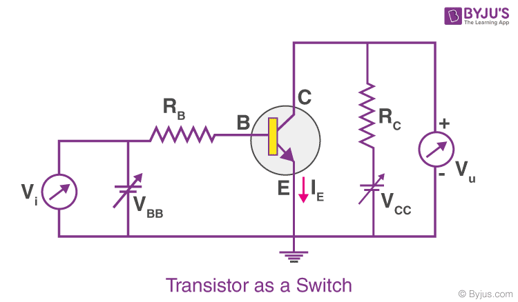
Working of Transistor as a Switch Circuit Diagram
It consists of an NPN transistor, a current-limiting resistor, and a load. Here is how the circuit works: Transistor: The NPN transistor, such as 2N2222 or similar, is a three-terminal device with emitter (E), base (B), and collector (C) pins. The transistor acts as a switch in this circuit.